How to Adjust Tension on Old Singer Sewing Machines
This article kindly submitted by Charles Day
The calibration of tension on Singer sewing machines is quite straight forward, but it does have to be performed in the correct order. The bottom tension MUST be correctly set BEFORE the top tension is adjusted.
Bottom Tension Adjustment
Under normal circumstances the bottom tension does not change in use, so once set correctly it should not have to be checked again. The need to adjust the bottom tension therefore mainly applies only to second hand machines you are not used to, or if the bobbin holder is changed for some reason.
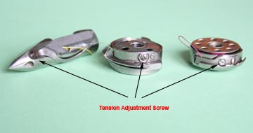
The adjustment principle of the bottom tension is similar for all Singer machines whether they use the vibrating shuttle boat type bobbin case (VS, 28, 128 etc.), the horizontally mounted removable bobbin case (15, 221, 222, 301) or the oscillating shuttle carrier with drop in bobbins (66, 99, 201 etc). In all cases the tension is provided by a small bent metal spring which traps the thread between the body of the bobbin case/carrier and the spring. The spring is slightly arched with a small adjusting screw that controls the pressure of the spring on the body and thus how much pull is required for the thread to slip between the two.

Lower Tension Adjusting Screw
If you have a spring balance, it is simply a matter of removing the bobbin holder, inserting and threading up a bobbin and then pulling on the end of the thread in the normal direction with the spring balance. The target figure should be around 30 to 40g. (1-1/4 to 1-1/2 oz) but it does not have to be too precise. However most people don’t have a spring balance handy, so alternatively you can tie a weight of the correct amount onto the thread and then jerk the bobbin gently upwards. This should cause 2 to 5 cm (1" to 2") of thread to slide through, but not for it to unwind freely.
If you don't have a set of small weights, then you can use digital scales to weigh sugar, sand etc into a small ziplock bag to use instead.
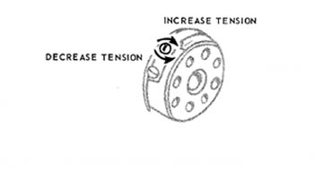
If the tension needs to be adjusted then it is simply a matter of tightening the screw near the centre of the spring to increase the tension, or loosening it to decrease the tension. Normally only slight movements are needed and so 1/16 to 1/8 of a turn should be ample steps before retesting.

Top Tension Adjustment
Once the bottom tension is set correctly, the top tension should provide a sufficient adjustment band to cater for the full range of materials and threads that may be used. If the lower tension is incorrectly set, then the machine may still sew but the upper tension may have to be at an extreme setting to compensate and this can cause tight or loose stitching, or thread breakage under some conditions.
Early Singer models had a simple arrangement of a knurled nut pressing a spring against 2 tension discs through which the upper thread passes. Tension adjustment is then a simple trial and error process of adjusting this nut so that a perfect lockstitch is formed. A fraction of a turn on the knurled nut in either direction is all that is usually required to suit different conditions.
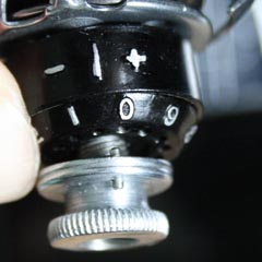
Later models used an upgraded upper tension control that incorporated a numbered dial into the adjustment nut. These should be calibrated so that the machine produces a perfect lockstitch on 2 layers of medium weight cotton fabric with the dial set between 4 and 5. If this is not the case then it needs to be re-calibrated so that it does.
Fortunately this is a simple process that doesn’t require any dismantling of the assembly.
The first thing to do is run a test stitch using 2 medium thicknesses of fabric to determine the correct position of the upper tension knob so that the machine makes a correct stitch having the right balance of top and bottom tension.
Then without turning the knob, use a thumb to push back firmly on the numbered ring on the tension assembly so that it moves against its spring away from the knob at the front and into its shroud.

Upper Tension Calibration
If you look carefully in the gap between the two parts you will see there is a series of 16 holes drilled around the front of the dial plate. You should also see that at one point in the rear flange of the knob there is a small shiny metal pin which projects out the back of the flange. When the dial plate is released this pin engages into one of the holes and allows the dial plate and knob to rotate as one. When releasing the dial plate it is necessary to check that the pin does correctly enter one of the holes, and if not to move it slightly until it does.
By turning the dial plate whilst it is pressed back, and then releasing it again, it is possible to alter the relationship between the knob which controls the tension and the dial which displays it. We are looking for a situation where one full turn of the knob and dial provides a range of tensions from maximum to minimum and so the basic default condition should be between 4 and 5. You therefore need to rotate the dial plate to this setting before releasing it.
Finally, retest the machine. If necessary repeat the adjustment process until it is right. It is not necessary to get it spot on because the default setting of 4-5 is only a starting point from which to work. However, in practice it is unlikely to ever need anywhere near the extremes of the upper tension range that the knob provides between its limits of 0 and 9.
